
How Do Vehicle Alignment Machines Work?
Alignment Machines Explained
- Parts of an Alignment Machine
- How to Operate Vehicle Alignment Machines
- Reading & Interpreting Data
- Need More Machine Info?
Understanding how to operate an alignment machine is crucial. Misalignments can lead to premature wear on tires and suspension components, potentially causing vehicle instability and hazardous driving conditions. Improper misalignments can also exacerbate existing issues, leading to even greater misalignment than before. This is why it’s important for technicians to understand how to operate these machines properly.
In this blog, we’ll cover the components of the alignment machine and how they work together, the basics of operating one, and how to interpret the data.
Parts of an Alignment Machine
Camera System or Sensors
The camera system or sensors on an alignment machine provide an image of the vehicle’s alignment. They ensure accuracy and allow a better view of the alignment parameters (toe, camber, and caster). Sensors also measure the angles of the wheels relative to each other and the vehicle.
Wheel Clamps
Wheel clamps hold the alignment sensors or cameras in place during alignment, providing a stable platform for measurements.
Turntables or Slip Plates
Slip plates or turntables allow the wheels to rotate freely during the alignment process. They allow the accurate measurement of the steering angles and help technicians make adjustments without resistance.
Steering Lock
The steering wheel must stay centered when aligning the wheels. The steering lock holds the steering wheel in a fixed position once the technician centers it.
Brake Pedal Depressor
Alignment machines require the vehicle brakes to be on for safety and accuracy. The brake pedal depressor keeps the brake pedal pressed during the alignment process to prevent the vehicle from moving. Technicians also use wheel chocks to hold the vehicle in place.
Lift/Ramp
The ramp provides easy access for driving the vehicle onto the machine, while the lift raises the vehicle high enough for the technician to work on and under the vehicle.
Calibration Bar or Frame
The calibration bar or frame tool is used to calibrate the alignment machine to ensure accuracy. It acts as a reference standard for the machine’s sensors and cameras, which can be checked and adjusted.
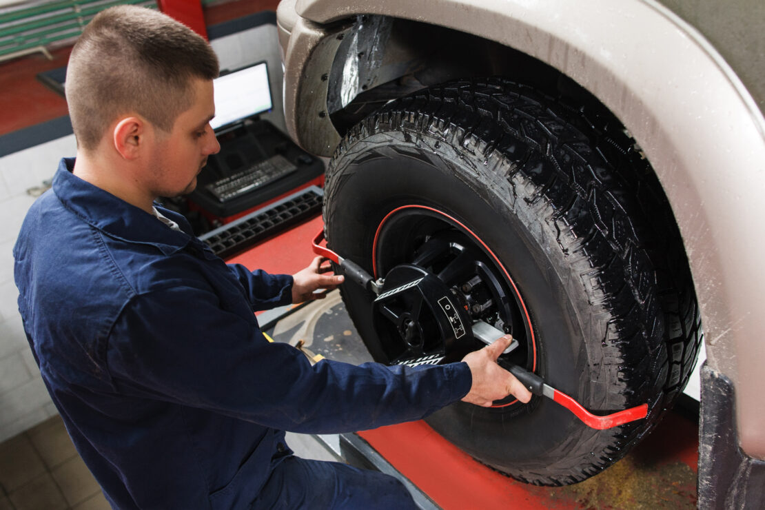
How to Operate Vehicle Alignment Machines

Most alignment machines operate similarly. However, various manufacturers may configure their alignment machines differently. Generally, it’s best to read the operating manual. Below are some of the basic operational rules that apply to most alignment machines.
- Raise the vehicle to allow easy access to the wheels. Most alignment machines have ramps that you can drive on.
- Attach the wheel clamps with the sensors or cameras to the wheels. They must be centered and vertical on the wheels, or you won’t get an accurate reading.
- Follow the instructions on the screen, ensuring the vehicle is in the proper place on the lift, and the steering wheel is straight.
- Apply the brake depressor and steering wheel lock.
- Follow the on-screen instructions. The alignment machine measures toe, caster, thrust, and camber angles.
- Follow the instructions on the alignment software to identify inconsistencies and adjust the angles where necessary.
- Print the before and after reports of the alignment.
Reading & Interpreting Data
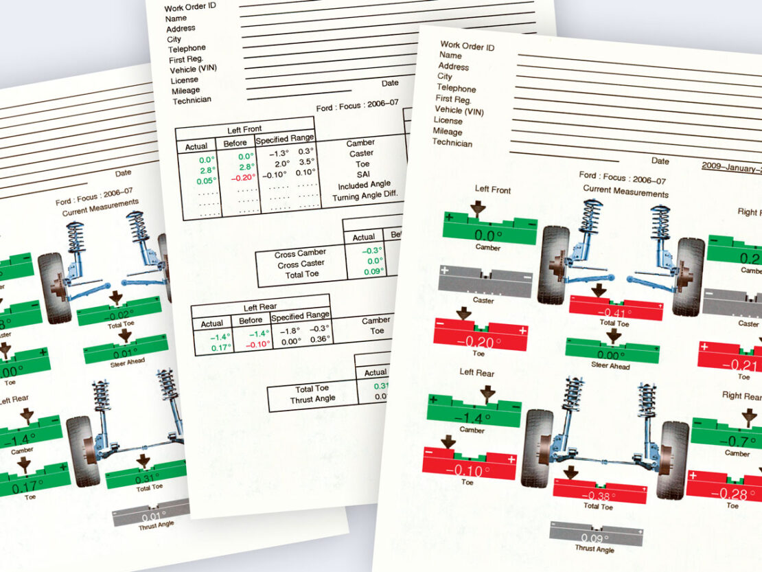
The software will show the alignment measurements in red, yellow, and green. If the adjustment is in green, it is correct. Yellow shows that it is within spec but not perfect. Even after an alignment, you may see yellow if certain adjustments cannot be made. Red means that the adjustment is out of spec and needs attention.
The adjustments include camber, caster, and toe.
Camber
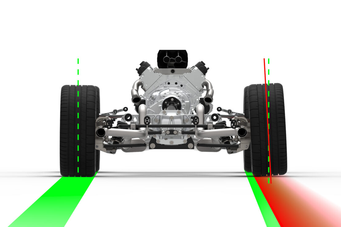
The wheel’s angle relative to the road is camber, which can be negative or positive. Positive camber is when the top of the wheel leans away from the vehicle, while negative camber is when the top of the wheel leans toward the center of the vehicle.
Out-of-spec positive camber causes wear on the outside of the tire, while negative camber causes wear on the inside of the tire.
Caster
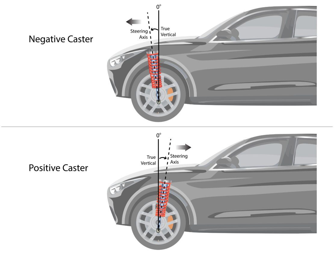
The caster measurement is the angle of the wheel from the top to the bottom of the steering axis, which is related to the suspension components at the wheel. An out-of-spec caster can cause the vehicle to drift and affect the steering wheel’s ability to return to position after a turn.
Positive caster pulls on the spindle. Often, the vehicle’s rear is lower than recommended, which can cause the front suspension to have positive caster, which usually causes pulling. Too much negative caster causes highly sensitive steering at high speeds. It also minimizes the ability of the steering wheel to return after turns.
Toe
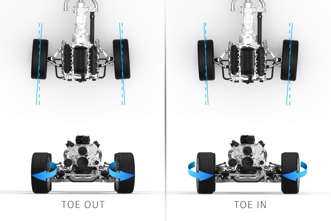
This angle measures the direction in which the wheels roll. Positive toe, or toe-in, is when the front of the wheels are turned in, much like turning the toes of your feet toward the center of your body.
Negative toe, or toe-out, occurs when the wheels are pointed toward the fenders. Tire wear and steering ability are affected if the toe measurements are not within specifications.
Learn More From Allied, Inc.
Allied, Inc. is a leading provider of vehicle lifts, alignment machines, air compression systems, brake lathes, and other diagnostic equipment from brands like Rotary Lift and Hunter.
We also install equipment for facilities and shops in Michigan and northern Ohio and provide basic training on using the equipment we install.
Please visit our blog for more resources, or contact us to learn more about our wheel alignment solutions.